Testing the Covidien FT10 Electrosurgery Medical Device
The importance of testing electrosurgery devices
Explore the importance of testing electrosurgery devices, how and why.
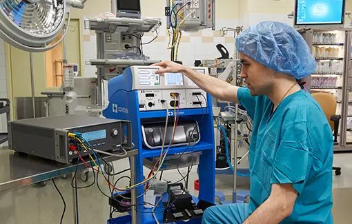
Getting called to test and verify an ESU in the OR requires quick and efficient response.
There are a lot of moving parts in a surgical procedure and it can fall to the Biomedical Equipment Technician to figure out where the system broke down. Maybe a bad pencil pinched or cut the cord, or there is a setup issue. There is so much equipment and so many people in the OR and it all must work together flawlessly. Sometimes you need to quickly test the ESU to troubleshoot issues.
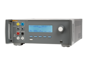
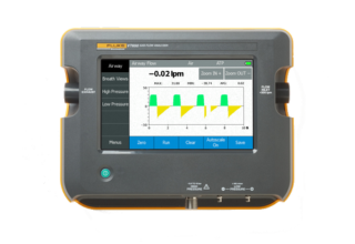
The QA-ES III can help by easily and quickly taking measurements to determine issues with the ESU.
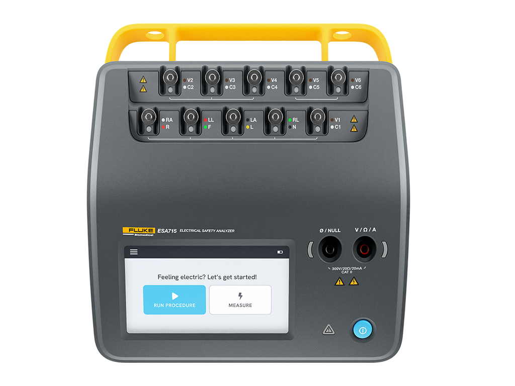
In this video, we will demonstrate the interconnect and output verification of a Covidien FT10 using the Fluke Biomedical QA-ES III Electrosurgical Analyzer.
All accessories used in this video are included with the QA-ES III.
Download this ESU Connections Quick Guide
How to test the Electrosurgery Medical Device
In this example we are verifying power output of the Covidien FT10 using the Fluke Biomedical QA-ES III electrosurgery analyzer
Verifying Monopolar Output Power
There is a challenge in that there are many devices on the market and remembering how to set up each can seem like a daunting challenge, there are a lot of cables, and for years we had to build our own testing devices and setups. The QA-ES III makes this easy buy including most of the cables that you will need for testing monopolar. Even if you need to utilize the manufactures handpiece, we have still provided alligators clips for safer connections. In monopolar, the energy leaves the ESU through a handpiece or pencil, performs the cut or coagulation, and then returns to the patient through the return electrode.
CQM is Contact Quality Monitor. This is the device responsible to verify that any energy that is dispersed from the ESU through the patient is returned to the ESU and ultimately ground. There are other terms we associate with QCM, REM Return Electrode Monitor, or ARM. CQM is the IEC and internationally accepted term for it. The QA allows for full-scale CQM testing by presenting a load range from 0 to 475 ohms by one-ohm increments. Off all the testing this is the one I feel is most important, the reason is that I want to ensure when they are using the ESU that I only get burnt in the location they are cutting and not under the return pad. A return electrode failure can cause an unwanted burn at the site, typically the CQM pad is placed on your upper right thigh or buttocks, if you get a burn their recovery can be a bit more painful to sit through, all means of pun intended.
- Once CQM is tested, the use of the REM Alarm Disabling lead, allows you to utilize the CQM cable on most modern devices. Now you only must remember one setup; also with the FT10, if you are not in service mode, the machine will not allow you to utilize a single foil CQM cable, so the duel foil with the disabling lead is the only option for non PM testing.
- Once CQM is set up, the QA gives you three easy to setup testing options. At least one option for every situation a tech could encounter.
- FT10 service mode. This is described in the video.
- Handpiece testing, utilizing the red variable high cable and alligator clip.
- Hand-free testing.
- Utilizing the hands-free adapter and footswitches
- Utilizing the built-in automation system.
- It is important to remember that Monopolar is monopolar, and most test setups are universal among modern devices.
The QA-ES III makes this testing easier by including most of the cables that you will need for testing monopolar. Even if you need to utilize the manufactures handpiece, we have still provided alligators clips for safer connections. In monopolar, the energy leaves the ESU through a handpiece or pencil, performs the cut or coagulation, and then return to the patient through the return electrode. The QA-ES III allows for full-scale CQM testing by presenting a load range from 0 to 475 ohms by one-ohm increments
In the first video we’re starting with the Power Up Check through testing the monopolar power output. This video will go step by step, including test setup, test setting, which cables to use and how to interconnect. The procedure covered include
- System Self-Test
- Verifying the Audio
- CQM testing should be in here as well
- Setting up to verify the power output
- Testing the Monopolar power output
Verifying Bipolar Power Output
Bi-polar testing can be easier than monopolar testing. In bi-polar mode, the energy typically leaves one tip of the handpiece and returns the opposite tip. The energy can be alternating polarity, much like AC power. Since the energy alternates polarity, you don’t need to worry about if the Red Variable High cable goes on the left or right. Simply connect the Red Variable High cable to one of the two larger ports and the variable low to the other.
Ligasure is much like Bi-Polar. We made it easy with the QA-ES III by providing cables that will quickly and easily connect to the two most outside ports of the Ligasure port. Once connected, simply follow the service manual for activation. Please note that this is the one scenario where you will have to either utilize the service mode to activate or a handpiece connected with alligator clips if you must simulate an actual event in a case. Please note if ever testing with products used in a case, they will be contaminated with bioburden and extra precautions must be taken to ensure safe testing.
The QA-ES III allows for multiple test setups.
- Service mode activation.
- Foot Pedal activation
- Automated QA-ES III activation
The connections for the QA-ES III have been made simple as our cable will connect directly to most Bi-Polar output, specifically the FT10.
In the second video we’re going to pick up with testing Bipolar Energy Channel Output. This video will go step by step including test setup, test settings, which cables to use and how to interconnect. The procedures covered include:
- Testing Bipolar Energy Channel Output
- Testing LigaSure/Bipolar output
Verifying Cross Coupling Power Output
Cross Coupling testing may seem complicated, but it can be easy. Knowing how to connect Mono-Polar, Bi-Polar, and LigaSure, will help. During Cross-Coupling testing, you should be following the service manual. You will connect to the specified output and specified return point, usually the FT-10’s ground pin, then activate another port. I.e. you may be connected to the Monopolar 1 output, but in-service mode you will activate Bi-Polar. This is done to ensure that no current will leak out of a non-specified port.
The service manual will guide you through this testing. The manufacturers give details such as diagrams and descriptions. In the third video, we’re going to cover Verifying Cross Coupling. This video will go step by step including test setup, test settings, which cables to use and how to interconnect. The procedures covered include:
- Mono 1 Current
- Mono 2 Current
- Bipolar Current
- LigaSure/Bipolar Current
High Frequency Leakage Testing
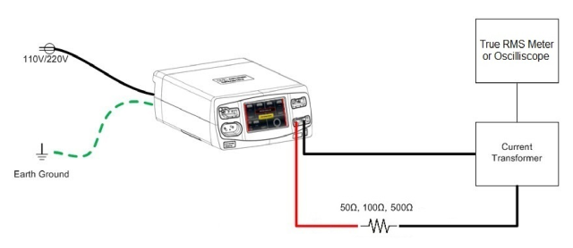
High Frequency Leakage testing could be confusing, some OEMs require special test set ups, and using jumpers between different ports of the analyzer to ground.
Testing the FT10 with the QA-ES III is a straight forward simple test setup. A few things to remember; The FT10 is a high frequency energy generator, the currents it produces are high frequency will almost act like radio waves.
- Make sure that the FT10 and QA-ES III are on separate non-conductive surfaces.
- Do not set the QA-ES III on top of the FT10
- Only utilize the cables provided with the QA-ES III they are a certain length and insulated in a way as to reduce interference.
- Ensure that the test leads are not twisted, or repeatedly crossed. They will act as an antenna and pick up false reading If you do.
The setup is simple.
- Connect the green test lead to the variable low, then connect the black alligator clip to the end. Use the green and black as green represents the ground, and black is typically neutral in a power supply.
- Connect the Red lead to the Variable High port, then follow the service manual and connect the other end to the specified energy output port.
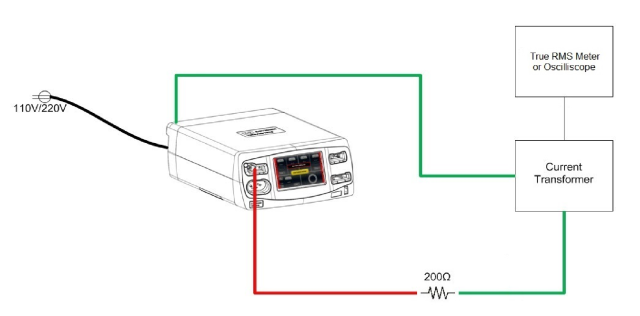
- On the QA-ES III you will want to go back to the main screen and then select HF leakage. The FT-10 manual will tell you to select 200 ohms from the energy output screen and you will get a reading; however, by selecting the HF leakage, the QA-ES III automatically applies a 200-ohm load, as well as directs the energy through energy rectifying circuit for a more accurate reading. This is like chassis leakage testing being routed through the patient load in your Safety analyzer.
- From here, simply follow the service manual for the desired ports and energy levels. Most reading should be less than 150mA, and again you may not have any reading for certain settings.
In this video of the series, we’re going to conclude the functional testing with Checking High-Frequency Leakage Current. This video will go step by step including test setup, test settings, which cables to use and how to interconnect. The procedures covered include:
- Checking Monopolar High-Frequency Leakage Current
- Checking Patient Return High-Frequency Leakage Current
- Checking Bipolar High-Frequency Leakage Current
- Checking LigaSure/Bipolar High-Frequency Leakage Current
Interested in learning more?
Follow-up with a product expert to learn more about our product line.
Best practices for testing the electrosurgery medical unit
Let’s start with the basics.
Electrosurgical units (ESU) use a high-frequency electrical current to cut tissue and control bleeding by causing coagulation. Tissue resistance to the high-density current causes a heating effect which results in tissue destruction. The electrical current is delivered and received through cables and electrodes. The electrodes may be activated by either a handpiece switch or a footswitch. The ESU may use a monopolar or a bipolar mode.
Monopolar vs Bipolar
In monopolar mode, electrical current is delivered to the patient via an active cable and electrode. As shown in Figure 1, current returns to the unit through a return electrode pad or plate to disperse the return current, thus preventing focused heat which can cause burns. In bipolar mode, two electrodes, typically the tips of a pair of forceps or scissors, serve as the equivalent of the active and dispersive leads in the monopolar mode.
Modes of Electrosurgery: CUT vs COAG
There are two types of cut modes: blended cut and pure cut. The pure cut is typically used for dissection only. In pure cut mode, the surgeon achieves a cut that is very similar to an incision produced by a medical scalpel. The cut is narrow, deep and the surgeon has little or no control over bleeding. This effect is obtained by high frequency and low voltage.
In blended cut mode, the surgeon achieves a much wider incision by heating up the tissue and letting it cool. This is achieved by lower frequency and higher voltage than pure cut. Coagulation is performed by using high voltage and low frequency. In COAG mode, heat is incapable of explosive vaporization, therefore, resulting in a thermal coagulum, also known as a clot. In COAG mode, the surgeon has more control over bleeding because the tissue is allowed more time to cauterize in between contact.
History of electrosurgery medical devices

photo: Arabic example of cautery use. (From the personal collection of James Tait Goodrich, MD, PhD, Albert Einstein College of Medicine, Bronx, NY)
The concept of using heat to stop bleeding goes back thousands of years. Throughout the centuries, researchers have constructed various devices that use electricity as a means to heat tissue and control bleeding.
Electrosurgery became more widely used in the late 1920s because of the urgent need to safely control bleeding in operative and invasive procedures. The evolution of the equipment has continued throughout its history to the devices of today that take the patient tissues into consideration during energy delivery for hemostasis.