Application Note: CT kV measurements on Somatom
CT kV measurements on Siemens SOMATOM CT Scanners
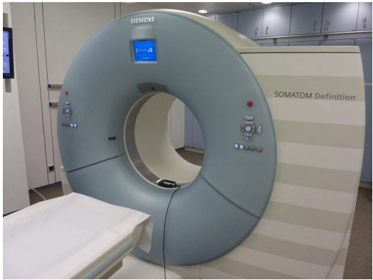
Picture 1: Overview of Siemens SOMATOM Definition CT Scanner with Unfors Xi R/F detector positioned on the gantry bottom
This application note explains how CT kV measurement shall be performed with an Unfors Xi R/F Detector and what correction factors shall be applied to gain the most accurate high voltage measurement result on Siemens SOMATOM CT Scanners.
Table of Contents
1 Background.................................................................................................................................2
2 Positioning the Unfors Xi R/F Detector..............................................................................2
3 Topogram Mode........................................................................................................................3
4 Correction Factors...................................................................................................................3
5 Technical Support Contact Details.......................................................................................4
1 Background
The Unfors Xi R/F detector was developed for a Radiographic and/or Fluoroscopic Xray machine utilizing a Tungsten anode tube with Aluminum filtration. Measurement algorithms for kVp, dose and HVL have been verified on Tungsten anode tubes with and additional filtration from 2.5 mm Al up to 1 mm Cu. While the Unfors Xi R/F detector is physically capable of measuring kVp on a narrow beam, such as a CT machine, the variations of beam shaping filters may alter the response of the measurement algorithms due to changes of the X-ray spectra.
The range of Siemens CT Scanners use Tungsten anode tubes with a metal window and combinations of various filter materials. These combinations cause different X-ray spectra slightly different than the scope for the Unfors Xi R/F detector. For measurements of kVp on these systems a set of corrections factors has to be applied to achieve an accuracy of 3 %. The needed corrections factors are based on the machine type and can be found in the tables below.
2 Positioning the Unfors Xi R/F Detector
Follow the instructions below to place the Unfors Xi R/F detector:
1. Place the Unfors Xi R/F detector on the bottom of the CT Scanners gantry. Note: The detector cable of the Xi R/F detector has to point to the “right” (if looking from the front side / patient table side into the gantry) See picture 1 and 2. Make sure that the Xi R/F detector is placed plane horizontal in the gantry. Use the Scanners laser cross to centre the Xi R/F high sensor area.
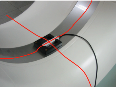
Picture 2: Center Unfors Xi R/F high sensor area using CT Laser cross
2. Connect the Unfors Xi R/F Detector to the Unfors Xi Base Unit.
3. Switch on the Unfors Xi Base Unit and select the “R/F high” detector.
4. Wait until the message “Zero adjust“ or “R/F high selected” disappears and “0 kVp” is displayed in the display of the Xi.
3 Topogram Mode
Follow the instructions below to perform measurements:
- Select “Topogram mode” at the CT Scanners console.
- Drive the patient table as far as possible out of the gantry.
- Select the X-ray tube position or (12°clock position).
- Select tube current = 300 mA
- Select Scan speed = 100 mm/s
- Select Topogram length = 128 mm
- Select the kV you want to test.
- Expose
- Read kV value from the Unfors Xi Base Unit display and multiply with corresponding kV-correction factor. (See chapter 4 in this document: Correction factors).
- Repeat the measurement twice and calculate the average value. At the same time you can test the HVL value. If you get the error message “Hi.Range” for 140 kV, turn the Unfors Xi R/F Detector 180° (now Xi cable is pointing to the left.) Repeat the measurement and use another correction factor*.
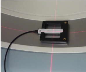
Picture 3: Only in case of a “Hi.Range” error message turn the detector 180°
4 Correction Factors
By using the following corresponding correction factors measurement uncertainty for kV is 3% and for HVL 10%.
| Emotion Duo / 6 / 16 and Spirit | Set kV | kV Correction factor |
HVL Correction factor |
| 80 | 1,00 | 1,13 | |
| 110 | 1,00 | 1,10 | |
| 130 | 1,01 | 1,13 |
| Sensation 4 / 16 | Set kV | kV Correction factor |
HVL Correction factor |
| Tube: Akron | 80 | 0,98 | 1,09 |
| 100 | 0,99 | 1,07 | |
| 120 | 1,00 | 1,05 | |
| 140 | 1,01 | 1,09 |
| Sensation 16 / 40 / 64 | Set kV | kV Correction factor |
HVL Correction factor |
| Tube: Straton | 80 | 0,96 | 1,10 |
| 100 | 0,95 | 1,10 | |
| 120 | 0,94 | 1,10 | |
| 140 | 0,93 | 1,10 |
| Sensation Open | Set kV | kV Correction factor |
HVL Correction factor |
| 80 | 0,98 | 1,00 | |
| 100 | 0,97 | 1,00 | |
| 120 | 0,97 | 1,02 | |
| 140 | 0,96 | 1,05 |
| Definition Dual Source, AS, AS+ and Flash | Set kV | kV Correction factor |
HVL Correction factor |
| 70 | 0,93 | 1,15 | |
| 80 | 0,95 | 1,15 | |
| 100 | 0,94 | 1,15 | |
| 120 | 0,91 | 1,15 | |
| 140* | 0,90* | 1,18* |
*) In case of receiving a “HiRange” error code from the Xi, do the following:
1. Reposition the Xi R/F detector 180 degrees, i.e. detector cable to the left.
2. Center the on the R/F high sensor area (laser line centered on the R/F high sensor area).
3. Use this correction factor: 0,93 for kV and 1,15 for HVL.
5 Technical Support Contact Details
In case you have any question regarding this application note or measurement issues please contact us at [email protected].