Frequently Asked Questions
The real-time display can be installed anywhere, it only needs a power outlet (network connection is optional). The dosimeters communicate with the display via radio. The radio communication range depends on the local environment and the Real-time Display settings (Service Manual) but is normally about 5-15 meters.
The X2 Base Unit can store several thousands of measurements.
- Swipe down from the home screen to see previous measurements.
- If the base unit has been turned off, or if you have switched to a different sensor, look in the measurement archive: Press the menu button and then Measurement archive. Select the session you want to take a look at.
- You can also use X2 View on a computer and select Import from Base Unit in the File menu and select from the calendar. See the X2 View manual for more details.
No, you have to send it to RaySafe for battery replacement. Fill in a Service Request to get it done.
To update firmware in the VT305 do the following:1. You will receive an update file (e.g. filename C0204000.S19) fromFluke Biomedical.2. Remove the micro SD Card from the VT305 and insert the card into your PC.3. Copy the update file onto the microSD Card.4. Remove the micro SD Card from the PC.5. Insert the micro SD Card back into the VT305.6. Restart the device (power on the VT305).7. The screen will show you the update's progress8. When the update is finished, the device will restart by itself.
The user manual for X2 is called "Help" and is integrated in the base unit. Press the menu button on your base unit and then "Help" to see the user manual for your system. You can also find video tutorials and pdf-manuals on the Product support page.
Yes, can combine i2 and i3 badges but be aware that measurement results may differ. We recommend that you replace the i2 badges with i3 ones as soon as possible to increase the efficiency of your RTSD.
Offset out of range is shown when the current in the ionization chamber fails to reach a stable level. Please make sure that:
the chamber is not irradiated during the stabilization or zero adjust phase, you are operating the instrument within its specified temperature range (15-35 °C).
If the problem persists, fill in a Service Request and send the detector for service.
I get too low readings with my Light detector. Why?
To retrieve measurements from the VT305 micro SD card:1. Remove the micro SD card from VT305 andinsert it into the appropriate SD card adapter(provided as a standard accessory with theVT305).2. Insert the micro SD card and SD card adapterinto the SD card reader, or insert the micro SDcard into the USB SD card adapter (providedas a standard accessory with the VT305).3. Connect the SD card to a computer.Questions and Answers6045 Cochran Rd, Cleveland, OH 44139 USA | Tel 440.248.9300 | Fax 440.349.2307 | Email: [email protected] | www.flukebiomedical.com4. Open the SetupReportFormatter.bat file fromthe VT305 micro SD card. This file has a macrothat imports data into your computer from theVT305.5. Open each .csv file in the DATA folder on themicro SD card. When a .csv file is opened, adialog box shows in the computer display andasks whether the data should be formatted.6. Click €˜Yes' to make a formatted report file. TheVT305 test report, like the one shown at theright, will be created.7. The .csv file can also be opened in anunformatted form using Microsoft™ Excel™.Click €˜No' and an unformatted .csv file will bedisplayed. The data can be formatted asdesired.NOTE: The files on the VT305 micro SD card cannot be renamed.
No, the i3 does not use a cradle like the i2. The improved i3 design lets you just use a USB cable to connect the dosimeter to the computer.
The dosimeter always measures and stores dose data on its internal memory, regardless of whether there is a display in range or not. You can view the dose history at any time by connecting the dosimeter to a computer running Dose Viewer.
To see the dose rate live, the dosimeter needs to be visible on a real-time display. The dosimeter shows up on any Real-time Display within communication range, it is not paired with a certain display.
The region inside the dashed red line is the active sensor area.
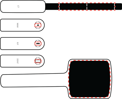
Note: Keep the active sensor area and its surroundings clean and free from stickers. Added material in the X-ray field may affect the measurement result.
No. The DXR+ has to be irradiated from the printed X-ray arrow and with a continuous field to give a correct result.
The VT305 is optimized for battery use. Ensure that the battery is fullycharged. The VT305 will operate on battery power for up to four hours ofcontinuous use. Shorter battery life will be experienced when the VT305 iscommunicating with computer applications such as the browser-viewedconfigurator, etc.
On the base unit side, use the Bluetooth device with USB connection that is provided by RaySafe (Laird BT820, pn: 1922064).
On the computer side there are various reasons for unstable Bluetooth connection such as incompatible hardware/software or environmental radio disturbances during measurements. Try turning off any programs on the computer that may interfere with the Bluetooth connection.
If the problem persists, you can try using a RaySafe Bluetooth USB device on the computer side as well. Turn off the internal Bluetooth.
Dose Manager is a software installed on your PC to see the history of dose exposures. You can see a dosimeter’s exposure over time and compare it to other dosimeters. With Dose Manager, you can also collect dosimeters exposure history from the Real-time Display and do not need to connect them individually to your computer. Dose Viewer compared to DoseManager can only show information for one dosimeter at the same time, and the dosimeter must be connected directly to your computer when you look at the history.
- No, i3 badges are not legal dose of record. The readings they record should be used for reference and behavior modification.
Remove the luminance tube and ensure that the white illuminance window is clean. You can clean it with a damp cloth. If the problem persists, fill in a Service Request and send the detector for service.
I have connected the mAs cable but don't get any readings. What can I do?
The fastest way to charge the base unit is to use the supplied charger. You can also charge with USB cable connected to a computer or a USB charger, but this will take longer.
The i3 has improved wear-ability with a replaceable reinforced plastic clip. The i2 had a metallic clip that could not be replaced.
No, the dosimeter is designed for maintenance-free usage throughout its lifetime.
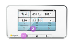
- When the instrument is in measurement mode, press SELECT (long press) until "Waiting... Aborting measurement" is shown.
- In the SETUP MENU, step (short press) to "Dose unit" and press SELECT until units are shown. Step to the desired unit and press SELECT until SETUP MENU is shown. The unit is now changed.
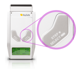
Note: If only Gray (Gy) is available, your instrument has been configured to comply with German regulations where the unit Röntgen (R) is not allowed.
The VT305 can be connected to mains power using the universal poweradapter and the appropriate prong-set (matched to the mains powerreceptacle). The power adapter connects to the VT305 via the USB cable.Alternatively, if a computer is being used during testing or documentation,you can connect the VT305 directly to the computer via the USB cable. Bothpower and data exchange are provided.
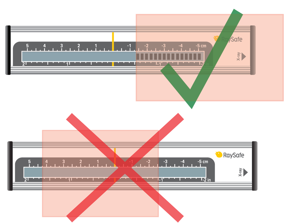
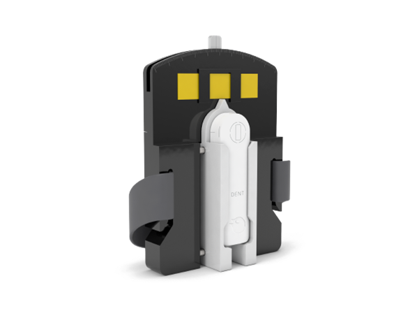
Panoramic dental machines can be challenging to measure on, primarily since the X-ray beam is narrow. Therefore, the positioning of the active sensor area is crucial.
Use DENT or R/F sensor.
Position the sensor in the exact center of the X-ray field, where you have the highest dose.
The positioning can be sensitive down to 0.1 mm. Use the RaySafe X2 panoramic holder to slide the sensor horizontally with high precision. Each mark on the scale represents 0.2 mm.
For details on how to use the panoramic holder, see the instruction video in our video library.
Dose Manager can be used with the new i3 dosimeters if you collect the dose information from your Real-time Displays using a network connection or with a USB memory. The i3 dosimeters unfortunately cannot currently be connected directly to Dose Manager by the USB cable.
- No, the feedback is visual. Because of this, it is best for the Raysafe Display to be located in an easily visible location for the staff.
Check that the cable is properly connected. Try another cable.
Swipe right from the home screen to access the setup. System language is found under X2 Base Unit. You will be asked to restart the base unit for the setting to take effect.
The i3 has room for naming, whereas the i2 does not.
The RaySafe Real-time Dosimeter: Approximately 1 year of normal use. The battery can be replaced. See the Installation and service manual for guidance.
The RaySafe i2 dosimeter: Typically 3-5 years, depending on usage. If the battery is out, contact your RaySafe representative or RaySafe Support Contact.
R/F high can be used for most measurements and is required for measuring kVp (as opposed to kV).
R/F low is optimized for low radiation intensity, typically during fluoroscopy measurements behind a phantom.
Use the VT305 with the Ansur VT Plug-In. You can use either a ready-for-usetest procedure or drag and drop one or more test elements from the Plug-Inonto the test template workspace in the Ansur software authoring screen(see Ansur Executive Operators' Manual for more information).Questions and Answers6045 Cochran Rd, Cleveland, OH 44139 USA | Tel 440.248.9300 | Fax 440.349.2307 | Email: [email protected] | www.flukebiomedical.com
The Dose Viewer version 1.1.13.0, delivered with the RaySafe i3, is backwards compatible with the RaySafe i2. Older versions of Dose Viewer need to be updated to support i3 Real-time Dosimeters.
The default Excel export format in X2 View is compatible with Xi View.
Unfortunately, this is not possible with the RaySafe i2/i3. This is something that we look in to for the future but currently only the Real-time Display can be used to visualize the exposure situation in real time.
- i3 badges will enter sleep mode after 9 minutes of not detecting any movement.

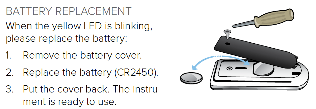
- If you just replaced the battery, this means that your ThinX is starting up. Be patient and wait for a while.
- If the screen appears when you are exposing the ThinX to radiation, you need to replace the battery (model CR2450). Follow the instructions in the user manual: ThinX RAD or ThinX Intra. We recommend using a battery from GP Batteries.
- Check that you are running the latest version of Xi View and remove older versions from your computer.
- During installation, make sure to tick the box "Install Windows 8 USB driver for serial port adapter".
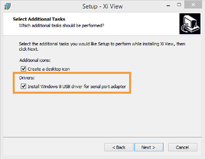
- In Xi View, select "ATEN USB to serial bridge" in the lower right corner. You may need to re-select it.
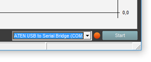
- In Xi View, press the "Start" button in the lower right corner and wait until the dot beside it turns green.
- If you have a Solo instrument, check that you have the RaySafe Solo PC kit.
Note: If your Solo instrument came with serial cable and usb-serial converter, it has the PC kit. If you wish to add the PC kit, contact Customer Service.
Swipe right from the home screen to access the setup. Press the name of the currently connected sensor to find the unit setting.
Note: If only Gray (Gy) is available, your instrument has been configured to comply with German regulations where the unit Röntgen (R) is not allowed.
Yes, they can, i2 and i3 dosimeters will show up on DoseAware base station screens and DoseAware dosimeters will show up on the i2 and i3 base stations screens. As the icons used for dosimeters are not the same for i2/i3 and DoseAware, the dosimeters might however appear differently.
To access the dose history recorded in the Real-time Display, tap on the row for your dosimeter on the display.
To access the internal dosimeter memory, connect the dosimeter to a computer running Dose Viewer.
The RaySafe Xi calculates kVp on the R/F high sensor if the intensity is high enough (around 10 mGy/s), otherwise kV average will be displayed. If the intensity is too low and you have no possibility to increase the tube current (mA), move the detector closer to the X-ray source.
Note: If your signal level is well above 10 mGy/s and you still do not get kVp, go to the SETUP MENU, select kVp mode, and make sure that kV/kVp is selected.
The VT305 uses a single measurement channel for all gas flow assessments.The display's (numeric and waveform screens) are auto-scaling and autorangingfor simple connection and use.
The RaySafe i3 has a customer replaceable battery, which prolongs the product life cycle up to 10 years. The RaySafe i2 badge needs to be replaced when the battery ends in <5 years.
Yes, all common mammography machines are supported. Just connect the X2 MAM sensor and measure to get dose, HVL and time on any beam quality. If you also want the tube voltage (kVp), you must select an anode/filter combination. Swipe left from the home screen to select.
Take a look in the Mammography coverage table to see which anode/filter combinations the X2 can give a kVp value for.
Yes, additional badges are available for purchase.
- Yes, i3 badges can be set to stay on all the time. This will drain the battery faster, however.
Read "SETUP OF BLUETOOTH COMMUNICATION" on page 6 in the Xi View User Manual. If you have established the Bluetooth communication as described in the User Manual but still have problems, try turning off any programs on the computer that may interfere with the Bluetooth connection. On the computer side, there are various reasons for unstable Bluetooth connection such as incompatible hardware/software or environmental radio disturbances during measurements.
Position and measure as usual. The X2 has full AMX4+ support.
Please visit www.RaySafe.com/i3/downloads, download and install the latest Dose Viewer that support i2 and i3 dosimeters.
No, the intended use for the i3 and i2 systems are to measure scattered radiation only.
It is enough to measure kV for one beam quality per machine, since the set kVp is independent of anode material and filtration. The Mammography coverage table lists what you can measure on different machines.
The Compliance parameter shown on the FULL (full test) numeric display ofthe VT PLUS is a dynamic value calculated from tidal volume and pressurevalues breath-by-breath. The Cstat parameter shown on the VT305 is a staticcompliance parameter calculated using the formula Cstat = VT / (Pplateau -PEEP) where Pplateau is the Inspiratory Pause Pressure. Not all ventilatorsprovide an inspiratory pause/hold function. If there is no plateau pressure,the VT305 Cstat displays"---" since a division by zero would result.
The EMC immunity in the i3 has been significantly improved over the i2, reducing possible interference.
Real-time measurements from up to eight dosimeters are shown simultaneously on the screen. The i3 has a sleep mode so only active dosimeters user show on the screen. The i2 dosimeters are always on and shown on the screen when in range.

Display: Luminance mode. For contact measurements on a display or view box.
0: Zero adjustment.
Light bulb: Illuminance mode. For measurements of ambient light or intensity from a collimator lamp.
- Prolonged life cycle
- improved EMC immunity
- better measurement specifications
- automatic sleep mode
- improved wearability.
The DXR+ works well placed on the examination table. Use as high kV as possible.
Note: Do not position the DXR+ on top of a magnification table, since the signal is too low there.
CRC error means that part of the data has been lost or altered in transit. This can happen when the distance is too long, or if something is interfering with the signal. Create a clear line of sight between the base unit and computer, or use a shorter distance.
Press the desired parameter from the home screen to go to full screen mode, then swipe left for the waveform. Waveforms are available for kVp, dose rate and mA.
Yes, you can.
Place your CT detector on a flat surface and restart the base unit. Do not touch or move the detector. If the "Stabilizing" message does not disappear within 5 minutes, fill in a Service Request and send the detector for service.
To save measurements press and hold the "O" button at the upper rightcorner of the VT305 display until the "Data saved toDATAxx.CSV" message is displayed on screen. This meansthat the measurement values have been saved to the microSD card in the VT305.
The i3 measurement performance is an improvement over the i2, and includes angular reception making it more accurate.
The waveform is accurate enough to assess whether there are problems in the X-ray tube or generator not disclosed by the numeric measurements. To obtain more accurate waveforms or to perform calibrations using the waveforms the 35080M199 X-Ray Scopemeter is recommended.
Yes. The IEC 61674 is about dosimeters with ionization chambers and/or semi-conductor (solid-state) detectors as used in X-ray diagnostic imaging and contrary to other kVp meters in the Fluke Catalogue the TNT12000 is compatible to this European Standard.
TNT 12000 uses a proprietary multi-element solid-state detector that simultaneously measures the variable attenuation experienced by adjacent elements to determine the HVL with just one exposure.
The TNT 12000WD was performing an internal amplifier nulling process but detected a start of X-ray shot and gave an error message.
Ion chambers can be added to the DoseMate using the Display, through the Excel Add-in, or with Ansur software.
Yes and it is standard on all TNT 12000 systems.
One. All measured parameters (kV, dose, time, HVL) are displayed all the time with each exposure, saving valuable setup time. Because TNT 12000 always defaults to the previous settings when powered down, many repetitive QA and calibration routines can be set up and completed by the stroke of a single on/off key.
Bluetooth wireless technology has several disadvantages that ZigBee does not. First, when turning on a Bluetooth-equipped device, the transmitting unit will search for available receivers and present a list from which the correct device must be selected. ZigBee units are paired, so upon scanning for detectors one does not get every wireless device in the local area, but only those ZigBee units paired with the companion TNT 12000 display or computer. Also, the power output is lower so ZigBee does not interfere with nearby medical devices, and greatly extends battery life of both display and detectors.
With the TNT 12000 solid-state detector or DoseMate dosimeter set to fluro mode, position either detector with the measuring side facing the X-ray tube at the prescribed distance from the focal spot. Completely block the image receptor using copper or lead sheets and begin the test.
TNT 12000 solid-state detector is slightly lower in accuracy (but much smaller, wireless, and easier to use than the Keithley Triad), and the DoseMate/ion chamber combination is equal to or greater accuracy compared with the Keithley Triad (both use the same ion chambers).
No, the 35035 is a standalone unit. The TNT12000 and the DoseMate dosimeter are both upgradable to include mA/mAs measurement functionality. These upgrades allow mA/mAs measurement values to be included in the diagnostic X-ray information displayed.
Both the Excel add-in and Ansur Test Automation software automatically capture test data and facilitate data management and reporting. The Excel add-in collects measured values and populates a customizable Microsoft Excel spreadsheet template; A MQSA-specific template is included for Mammo applications. Ansur provides a visually-guided inspection procedure that reduces human error with step-by-step visual instructions, auto-configuration of compatible test instruments, auto-data collection of measured values from compatible test instruments, auto-comparison of measured values against pre-determined test limits, and objective determination of Pass/Fail. All inspection results are included in a single, test result file and customizable test report that can be printed or stored digitally. Ansur Test Automation software is also compatible with a range of CMMS software systems. All users may utilize the Excel add-in for reporting purposes. Users who need to standardize testing and reporting procedures (especially when performed by multiple associates) and minimize risk of human error benefit from Ansur Test Automation software.
Turn Auto-reset OFF and the DoseMate electrometer will accumulate dose values. Turn Auto-reset ON to allow the DoseMate electrometer to reset between exposures.
Each of the two sets of cross-hairs on the TNT 12000 solid state detector are marked as to their use. The gray-colored cross-hairs are for Rad/Fluro, while the red-colored cross-hairs are for Mammo. These aid in centering the detectors in the X-ray beam
Yes it is possible to perform kV and other X-ray tube parameter measurements for the standard dental X-ray tube (TNT12000WD may need to be attached to a camera tripod to hold it in place in the beam.) Panoramic dental X-ray, like other modalities where the X-ray tube is rotating/moving, requires the tube be kept in place (not moving) to measure X-ray tube parameters. If dose is the parameter of interest, use DoseMate and an appropriate ion chamber capable of detecting X-ray energy in a 360 o arc about its center. There is no special calibration needed in either case.
Use the DoseMate and the 15 cc ion chamber in the table Bucky tray to obtain time measurements.
Any firmware or software upgrades that do not affect calibration of the TNT 12000 are available on the Fluke Biomedical website under Support: Software Downloads.
There are two options.
- Standard: Mo/Mo for Mammographic and W/Al for Diagnostic-standard calibration
- Optional: Mo/Rh, Mo/Al, Rh/Rh, Rh/Al for Mammographic
No. One should pick the data-collection and display device that best meets the needs of particular application scenarios. For example: 1st call triage of reported X-ray system problems might be best managed using the TNT 12000 display unit and the appropriate detector or combination, while scheduled inspections or calibration might best be served by an Ansur visually-guided inspection procedure, or an assessment of image quality vs. dose might best be served by the DoseMate/Excel Add-in combination.
No. The display unit will work with any TNT 12000 solid-state detector or DoseMate.
Use the TNT 12000 solid state detector in Fluro-mode.
PPV means practical peak voltage and is a measurement used outside the USA for assessing X-ray tube performance.
No. The TNT 12000 display shows only the last measurement. If measurements need to be saved, the Excel Add-in is recommended. If both measurements and other inspection results in an overall inspection procedure need to be saved, then a visually-guided inspection procedure should be created using the Ansur TNT 12000 Plug-in. This inspection procedure documents the entire process and all inspection results (physical/visual inspection, mechanical inspection/adjustments, electronic measurements, lubrication steps, replacement of consumable items, etc.)
A minimum of 500 mR/min doserate is needed to get accurate kV results.
There are five different possibilities:
- Blue - Display or detector is connected to a power source and the battery is fully charged.
- Green - Display or detector is connected to a power source and the battery is charging.
- OFF - Display or detector is not connected to a power source and is operating on battery power.
- Yellow - Display or detector battery has approximately 20% of charge left.
- Red - Display or detector battery has approximately 10% of charge left and will turn off in two minutes.
A 15 cc ion chamber is useful for Radiographic X-ray systems and Mammographic X-ray systems; a 150 cc ion chamber is useful for Flouroscopic X-ray systems (e.g., input dose to image intensifier), Scatter assessment, and any situation where the increased sensitivity of the chamber allows measurement of lower dose-rates.
The Impulse 7010 only works with Fluke Biomedical's newest defibrillator/external pacer analyzer, the Impulse 7000DP. It will not function with legacy Fluke Biomedical analyzers such as Impulse 4000, QED6, QA40/45, or with competitor products.
Yes. The manufacturer of the NiMH battery cells used in the Impulse 6000D/7000DP specifies a typical loss of 10 % of battery charge after 500 charge-discharge cycles, which is approximately two years of daily use. Battery charge capacity also degrades with time, so even a seldom-used unit will lose some battery charge capacity. The Impulse 6000D/7000DP battery power feature was designed conservatively to maximize the probability of the battery pack performing satisfactorily well beyond two years.
The answer to this question is somewhat counterintuitive. Battery pack gas-gauge ICs, such as the one used in the Impulse 6000D/7000DP, use a complex algorithm to estimate battery-charge state, taking into account time, temperature, and current flow. The self-discharge estimation (i.e., how much charge the battery loses over time during periods of non-use, sometimes called "shelf-life") is particularly sensitive to battery chemistry, and the shelf-life of today's NiMH cells is significantly longer than the algorithm built into the gas-gauge ICs can accommodate.
When an Impulse 6000D/7000DP is left idle for a few weeks and then powered-on, the battery charge level might be reported as 55 % when the true charge level might be 80 %. If the battery is then completely charged, which requires a 20 % increase in battery charge level, the charge level is only reported as 75 % (55 % plus 20 %).
To correct the reported charge level, use the "Train Battery" feature. To access this feature, press the [SETUP] key, then the [F1] softkey(labeled "Battery"), then press the [F3] softkey (labeled "Train Battery"), then follow the instructions presented on the screen. This procedure can take overnight to complete.
To keep the reported battery charge level as accurate as possible during extended periods of non-use, the Impulse 6000D/7000DP should be left connected to mains power via the battery charger with the unit powered off in an ambient temperature of 15° C to 26° C (60° F to 78° F). This will continuously trickle-charge the battery (the charge-status LED on the rear panel will be green) to keep both the actual and estimated battery charge level at 100 %.
The ZigBee dongle is a HID, Human Interface Device, and it does not require a driver.
A blinking red charge-status LED indicates a pending charge and should normally last a few seconds before turning solid red. If the blinking continues, the battery-charging circuit has determined that conditions are not correct to initiate the battery-charging cycle. The battery will not be charged if the battery temperature is too cold or too hot. The battery should be charged in an ambient temperature of 10° C to 40° C (50° F to 104° F)
Also, the battery will not be charged if the battery voltage is too low, which can happen if the Impulse 6000/7000DP has been stored for an extended period of time with a fully-discharged battery. In the "Charge Pending" mode, the battery-charging circuit charges the battery at a low rate, which will eventually bring the battery voltage high enough for the normal charge cycle to begin.
No! The SigmaPace1000 is designed to test only one ventricular transcutaneous pacemaker or one transvenous pacemaker at a time. The transvenous pacemaker can be one of these types:
Testing defibrillator energy delivery using internal paddle electrodes, which typically have a curved shape unlike external paddles whose electrodes are flat, is best done using the special internal discharge paddle contacts accessory.
Part Number: 3065438
Description: Internal discharge paddle contacts (set of 2)
Do not use conductive gel when testing internal discharge defibs; the same applies to external discharge adhesive electrodes. The conductive electrolytic gel is only used on patients to improve the contact to the external paddles. The analyzer has very low-resistance contacts that do not require gel.
Clinically, the non-sterile conductive gel is never used inside the patient's thoracic cavity during open heart procedures with the internal discharge paddles. The internal discharge paddle adapters for the Impulse 7000 can be eTO2 gas sterilized and used on sterilized internal discharge paddles, but non-sterile adapters may be used on non-sterilized internal discharge paddles as a pre-test prior to the sterilization process of the paddles.
IMPORTANT These adapters can not be steam sterilized, as it creates too much heat for the plastic parts.
Monophasic waveforms used in the legacy defibrillators, biphasic waveforms in most of today's technology, as well as pulsed biphasic waveform, an emerging new technology.
- Age of battery pack. The battery pack will lose some charge capacity over time.
- Use of the backlight display function. This option discharges the battery pack faster.
- 3. Operating the unit at the upper end of the specified operating temperature range, causing the internal fan to power on more often. This may especially be observed with multiple, rapid, high-energy defibrillator pulse discharges into the unit.
Sampling rate should be 5 times the X-ray system frequency for accurate kv waveform analysis. The GE AMX4, the most ubiquitous mobile in the world, operates at 2 kHz. Systems like the Unfors Xi and RTI Piranha sample at around 2 kHz and thus cannot adequately sample an AMX waveform.
If the Impulse 6000D/7000DP is turned on, make sure the "Charge Battery" setting is set to "Yes" on the "Set Up: Battery" screen (refer to the operating manual for details). If the Impulse 6000D/7000DP unit is turned off, the LED should glow red when the external charger is connected correctly and mains power is present.
The SigmaPace1000 is designed to test external cardiac pacemakers only. The two compatible types of external cardiac pacemakers are these:
- Transcutaneous: This type of pacemaker (typically built into a cardiac resuscitation unit with a defibrillator) has output currents ranging from 30 to approximately 200 mA. External adhesive electrode pads are attached across the patient's intact chest to deliver the energy. (The Impulse 4000 also tests this category of external pacemaker.)
- Transvenous: This typically small handheld unit, powered by a single 9-volt DC battery, generates pacing pulses at levels from 1 to approximately 25 mA. This type of pacemaker is available in many different configurations from simple single chamber models to more sophisticated AV sequential dual chamber models. The pacing electrodes are introduced via the patient's venous circulatory system via a temporary indwelling cardiac catheter connected directly to the heart.
Plug the battery charger accessory included with your analyzer into the charger input on the rear panel and plug the mains cord into the charger unit and into mains power. The charge-status LED, visible from the rear panel, will glow red to indicate the battery is charging. The LED will turn green when charging is complete. A full recharge takes approximately four hours or less.
The basic difference is the direction of current flow between the defibrillation pads. With a monophasic waveform, the current flows in only one direction. With a biphasic waveform, the current flows in one direction, then reverses and flows in the opposite direction. Lower energy is used in biphasic waveforms.
No. For safe and reliable operation, the battery charger MUST have a good earth ground when connected to the Impulse 6000D/7000DP, and vehicle electrical systems inherently lack an earth ground. For battery charging only (with the Impulse 6000D/7000DP turned off, and no other connections to the Impulse 6000D/7000DP unit other than at the charger input jack), using a DC-to-AC inverter to power the battery charger may yield consistent battery charging, depending on the quality of the inverter used. As of this writing, Fluke Biomedical cannot recommend the use of a DC-to-AC inverter for battery-charging-only use with the Impulse 6000D/7000DP.
Ensure the solid state detector is facing the tube and is perpendicular to the X-ray tube axis. For under-table tubes, this means that the solid state detector should be placed face-down on the X-ray table.
When combined with the high-end functionality improvements of the Ansur test automation system, your Fluke Biomedical analyzer provides a solution-based approach to complete analysis of the medical device under test. Fluke Biomedical test equipment with Ansur automation solutions create standard work using test templates/sequences based on customer's written test procedures, manage test procedures by allowing both manual and visual automated test sequences, and integrates all test results into a single test report, which can be printed or archived.
No! The SigmaPace1000 dual channel input jacks on the SigmaPace1000 are protected against an occasional application of a high-voltage defibrillator output. The analyzer's protection circuitry is designed to withstand accidental discharges at 360 J.
No. For safe and reliable operation, the battery charger MUST have a good earth ground when connected to the Impulse 6000D/7000DP, and vehicle electrical systems inherently lack an earth ground. For battery charging only (with the Impulse 6000D/7000DP turned off, and no other connections to the Impulse 6000D/7000DP unit other than at the charger input jack), attempting to charge from a 12 V vehicle gives inconsistent results and therefore cannot be recommended.
No. Different waveforms perform differently depending on their shape, duration, voltage, current, and response to impedance. Different biphasic waveforms are designed to work at different energies. Impulse 6000D/7000DP measures the monophasic waveforms used in the legacy defibrillators, biphasic waveforms used in current technology, as well as pulsed-biphasic waveforms, an emerging technology.
No. Replacement of the battery pack in the Impulse 6000D/7000DP requires disassembly of the unit. Impulse 6000D/7000DP owners who send their units to a Fluke Biomedical Authorized Service Center for periodic calibration may want to consider requesting replacement of the battery pack as preventative maintenance, which can be performed for a nominal charge.
Cables require time to set up and put away after use, which reducess, and can be bumped or stepped on during operation-causing erroneous readings, delays and other productivity challenges.
Impulse 7010, Defibrillator Selectable Load Accessory, in conjunction with Impulse 7000, Defibrillator/External Pacer Analyzer, is specifically designed by Fluke Biomedical to allow defibrillator manufactures and end users to comply with portion of IEC 60601-2-4 and AAMI DF80 standards.
Impedance in humans has been shown to vary anywhere from 25 to 180 ohms with the average impedance of an adult around 70 to 80 ohms according to an AAMI study. A well designed defibrillation waveform must measure patient impedance and adjust the waveform shape and duration accordingly to optimize waveform performance across the range of anticipated impedance values.
The "Section 6.8.3" of the IEC 60601-2-4 standard and AAMI DF80 standard require defibrillators to be tested on different resistant loads of 25, 50, 75, 100, 125, 150, and 175 ohms to ensure proper energy is delivered to patients with different impedances. Impulse 7010 is also the only testing tool to test defibrillators beyond 175 ohms. A 200 ohms option gives manufactures the capability to test defibrillators under extreme impedance conditions. In addition, interface with Fluke Biomedical Ansur, PC-based automation software, allows for standard, streamlined and time-saved operation and total digital data management.
Use of Impulse 7010 is easy. Simply connect the Impulse 7010 output connectors to the input connectors of Impulse 7000 as shown in the figure below. The various connection combinations available through the Impulse 7010's rotary switch provide eight different loads for a defibrillator discharge.
Yes. Actually, to keep the reported battery charge level as accurate as possible during extended periods of non-use, it is recommend that the Impulse 6000D/7000DP be left connected to mains power via the battery charger with the unit powered off, in an ambient temperature of 15° C to 26° C (60° F to 78° F). This will continuously trickle-charge the battery (the charge-status LED on the rear panel will be green) to keep both the actual and estimated battery charge level at 100 %.
If the Impulse 6000D/7000DP cannot be kept connected to the battery charger during periods of non-use, the battery should be charged at least once a month. A unit with a discharged battery that is stored for an extended period of time will result in the battery becoming over-discharged, which is likely to result in permanent damage to the battery.
Impulse 7000DP tests the full function of transcutaneous pacers, but not transvenous pacers. For transvenous pacer testing, try the SigmaPace 1000 or DALE400 analyzers.
No. For safe and reliable operation, the battery charger supplied with the Impulse 6000D/7000DP MUST be used when operating from mains power, or when operating and charging the battery at the same time.
A minimum of 500 mR/min doserate is needed to get accurate kV results.
The fan on the back of Impulse 6000D/7000DP is controlled by a thermostat IC. The thermostat utilizes an on/off control (i.e., not linear or continuous control). The thermostat IC is located next to the defibrillator load resistor.
There are two temperature thresholds. The lower threshold is set at about 40° C (104° F) and the upper threshold is set at about 50° C (122° F). When the temperature exceeds the low threshold, the fan turns on. When the temperature exceeds the upper threshold, a warning message is displayed and the unit will not make any further measurements until the temperature has dropped below the upper threshold.
On the Impulse 6000D/7000DP, the internal battery pack contains a gas-gauge IC that monitors the battery-charge level. This gas-gauge IC reports the charge level as one of sixteen levels, from 0 % to 100 %. The Impulse 6000D/7000DP reports the battery-charge level in 5 % steps, from 0 % to 100 %. Therefore, five of the 5 % steps aren't used (15 %, 35 %, 50 %, 70 %, and 90 %). The "Power = 50%" message is an indication that the microprocessor was unable to communicate with the battery pack. If this message persists, the battery pack is probably defective.
When combined with the high-end functionality improvements of the Ansur test automation system, your Fluke Biomedical analyzer provides a solution-based approach to complete analysis of the medical device under test. Fluke Biomedical test equipment with Ansur automation solutions create standard work using test templates/sequences based on customer's written test procedures, manage test procedures by allowing both manual and visual automated test sequences, and integrates all test results into a single test report, which can be printed or archived. Biphasic Monophasic
No. The Impulse 6000D/7000DP was designed and tested to meet all its performance specifications at any battery-charge level when operating from mains power or when operating from mains power while charging the battery.
ZOLL M Series and PD14000 use different algorithms to output pacing function. The default ZOLL MEDICAL pacer selection in Impulse 7000 uses ZOLL M Series algorithm to detect pacer output from ZOLL pacers. We recommend that customer choose ZOLL MEDICAL brand under Impulse 7000 PACER testing function when testing ZOLL M Series, but choose DEFAULT ALGORITHM when testing ZOLL PD14000 to get accurate readings.
Select the manual waveforms icon in the Excel Add-in tool bar and then select the waveform (and how much of the waveform) to be viewed.
This is not necessary. The battery does not exhibit a "memory effect". After multiple partial charge-discharge cycles, or if the unit is unused for an extended period of time without the charger active, the battery level indication may become inaccurate (i.e., out-of-sync with the actual battery charge level). Completely discharging the unit before charging it will resynchronize the battery charge level indication.
No. The SigmaPace1000 was designed to test a wide range of external pacemaker parameters. It is not intended for use with internal pacemakers. Manufacturers of internal cardiac pacemakers offer sophisticated test systems that are designed for their specific brand and range of available internal pacemaker models. These test systems typically perform specialized functions such as tissue impedance measurement, and also program operational parameters of these implantable cardiac pacemakers. These diagnostic test systems are utilized during surgical implantation procedures and have direct contact to the patient's heart.